You can record audio from the four channels (CH1/CH2/CH3/CH4) in synchronization with the video images on this camera recorder.
Audio Recording
Select from the options below to record the audio.
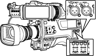
Microphone connected to [MIC IN] terminal (XLR 5-pin)
Microphone or line input connected to the [AUDIO INPUT1] terminal (XLR 3pin)
Microphone or line input connected to the [AUDIO INPUT2] terminal (XLR 3pin)
Setting the Number of Recording Channels
Set the number of recording channels in [System]  [Record Set] [Record Format] [Audio].
Selecting Audio to Be Recorded in Each Channel
Select the audio to be recorded in CH1/CH2/CH3/CH4.
|
- |
Switch Setting |
Connected Devices |
|---|---|---|
|
CH1 |
FRONT |
Audio input of microphone 1 from [MIC IN] terminal |
|
REAR |
Audio input from [AUDIO INPUT1] terminal |
|
|
WIRELESS |
Audio input of CH1 from the “UniSlot” wireless receiver |
|
|
CH2 |
FRONT |
Audio input of microphone 2 from [MIC IN] terminal |
|
REAR |
Audio input from [AUDIO INPUT2] terminal |
|
|
WIRELESS |
Audio input of CH2 (or CH1) from the “UniSlot” wireless receiver |
When the switch setting is set to “FRONT”
Audio recording is performed according to the setting in [A/V Set] [Audio Set] [Front Mic Select]/[Front Mic Power]/[Front Mic 1 Ref.]/[Front Mic 2 Ref.].
Caution
Set [Front Mic Select] to “Stereo M/S” to convert the audio signal to stereo (L/R) signal for recording when a Mid/Side direct output microphone is connected.
Do not set to “Stereo L/R” or “Mono” when an L/R out stereo microphone or a monophonic microphone is connected.
When the switch setting is set to “REAR”
Select the audio input to the [AUDIO INPUT 1/2] terminal using the [AUDIO INPUT 1/2] switch.
|
Setting |
Description |
|---|---|
|
[LINE] |
Use this setting when connecting to an audio device or other equipment. |
|
[MIC] |
Use this setting when connecting to a dynamic microphone. |
|
[MIC+48V] |
Use this setting when connecting to a microphone (phantom microphone) that requires a +48 V power supply. |
Memo
When “LINE” is selected, configure the reference input level in [A/V Set] [Audio Set] [Rear Line Ref.].
When “MIC” or “MIC+48V” is selected, set the reference input level in [A/V Set] [Audio Set] [Rear Mic 1 Ref.]/[Rear Mic 2 Ref.].
Caution
When connecting a device that does not require a +48 V power supply, make sure that it is not set to the “MIC+48V” position.
When the [AUDIO INPUT 1/2] switch is set to “MIC”, make sure that a microphone is connected to the [AUDIO INPUT 1/2] terminal. If you increase the recording level when a microphone is not connected, noise from the input terminal may be recorded.
When a microphone is not connected to the [AUDIO INPUT 1/2] terminal, set the [AUDIO INPUT 1/2] switch to “LINE”.
When the switch setting is set to “WIRELESS”
Recording is performed as follows according to the setting in [A/V Set] [Audio Set] [Wireless Channel].
|
|
“UniSlot” Wireless Receiver |
|
Camera |
|---|---|---|---|
|
Single: |
CH1 |
|
CH1/CH2 |
|
Dual: |
CH1 |
|
CH1 |
|
CH2 |
|
CH2 |
Caution
Power is supplied to the “UniSlot” wireless receiver when any of the CH1/CH2/CH3/CH4 switches is set to “WIRELESS”.
Adjusting the Audio Recording Level
You can select to adjust the audio recording levels for each of the four channels (CH1/CH2/CH3/CH4) manually or automatically.
Manual Adjustment Mode (Manual Adjustment)
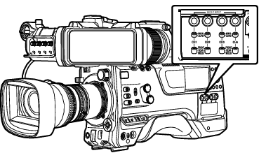
The manual adjustment mode is enabled by setting the [AUDIO SELECT CH1/2/3/4]-[MANUAL/AUTO] selection switch on this camera recorder to “MANUAL”. The audio level for each channel can be configured in [A/V Set] [Audio Set] [CH1 Audio Level](/2/3/4) [Front]/[Rear/Wireless].
You can adjust the level manually during the recording, recording standby, and stop modes.
Memo
The audio setting in Full Auto mode can be configured in [Camera Function] [Full Auto] [Audio Set].
Set the [AUDIO SELECT CH1/2/3/4]-[MANUAL/AUTO] selection switch to “MANUAL” for the channel to be adjusted manually.
Turn the adjustment knob corresponding to the channel to adjust the level.
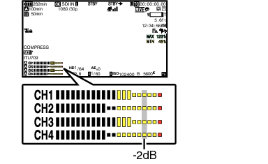
When [A/V Set] [Audio Set] [CH1/2 DRC]/[CH3/4 DRC] [Threshold Level] is set to “Off”, adjust such that the audio level meter -2 dB does not light up even for loud sounds.
Memo
The [Threshold Level], [Attack Time], [Decay Time], [Mode], etc. of the compressor can be configured in [A/V Set] [Audio Set] [CH1/2 DRC]/[CH3/4 DRC] for the audio to be recorded.
DRC (Dynamic Range Compressor)
The limiter operates according to the setting in [A/V Set] [Audio Set] [Limitter] [CH1](/2/3/4).
When [Limitter] is set to “Off”, the limiter function is disabled even when the [MANUAL/AUTO] switch is set to “AUTO”. This may cause the OVER indication of the level meter to light up.
The reference audio level is configured in [A/V Set] [Audio Set] [CH1/2 Audio Ref. Lv.] (common for CH1/2)/[CH3/4 Audio Ref. Lv.] (common for CH3/4).
Automatic Adjustment Mode
Set the [AUDIO SELECT CH1/2/3/4]-[MANUAL/AUTO] selection switch to “AUTO” or press the user button assigned with “Full Auto” to set Full Auto mode to off. This activates the Automatic Adjustment mode and the audio recording level is configured automatically according to the input level.
The audio setting in Full Auto mode can be configured in [Camera Function] [Full Auto] [Audio Set].
Memo
If [A/V Set] [Audio Set] [CH1/2 DRC]/[CH3/4 DRC] [Threshold Level] is set to a value other than “Off”, the compressor operates according to the value set.
References on DRC (Dynamic Range Compressor) and Limiter
DRC and Limiter Configuration Block Diagram
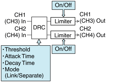
DRC Operation
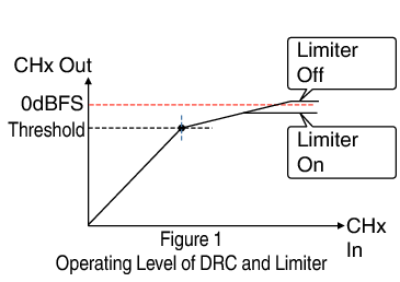
This operation helps to prevent the recording level from reaching saturation (0 dBFS) by slowing down the gain changes when the excessive sound input exceeds the threshold level.
[CH1/2 DRC] and [CH3/4 DRC] settings
Threshold Level:
This is the point when the gain changes slowly. (See Figure 1)
Lowering the threshold level will make it difficult for the recording level to become saturated but this will decrease the sound volume.
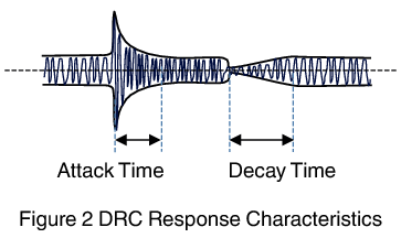
Attack Time:
This is the response time from when the sound exceeds the threshold level until the level is compressed. (See Figure 2)
“Fast” will result in fast response time and “Slow” will result in slow response time.
Decay Time:
This is the response time from when the excessive sound input falls below the threshold level until the level compression operation is canceled. (See Figure 2)
“Fast” will result in fast response time and “Slow” will result in slow response time.
Mode:
CH1 (CH3)/CH2 (CH4) operate independently (mono) when “Separate” is selected.
CH1 (CH3)/CH2 (CH4) operate in tandem (stereo) when “Linked” is selected. The level difference between CH1 (CH3)/CH2 (CH4) remains constant.
“Fast” and “Middle” in the Attack setting are suitable for speech. “Middle” and “Slow” are suitable for music.
“Fast” and “Middle” in the Decay setting are suitable for speech. “Middle” and “Slow” are suitable for music.
When using a stereo microphone with CH1 (CH3)/CH2 (CH4), configure the Mode setting to “Linked”.
To record different audio with CH1 (CH3)/CH2 (CH4), configure the Mode setting to “Separate”.
Limiter Operation
A high speed response limiter that does not exceed the saturation level (0 dBFS) for sharp increase in the sound input not trackable by DRC.
[Limitter] settings
On:
Enables the limiter separately for CH1/CH2/CH3/CH4.
Off:
Disables the limiter separately for CH1/CH2/CH3/CH4.
AUTO/MANUAL SW Set:
The limiter is enabled when the [MANUAL/AUTO] selection switch is set to “AUTO” and disabled when “MANUAL” is selected.
![]()