This mounts the camera on the ceiling and secures it so that it does not fall.
VN-H657U
TOPCamera
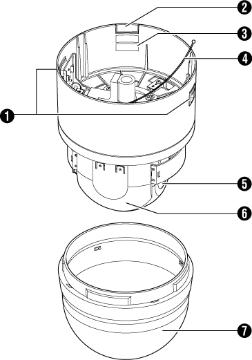
Camera fixing lock knob (x2)
Cable cover
To pull the cables from the side and mount the camera, remove the cover.
[MAC address] indication
The MAC address is a unique physical address of the product. This address cannot be altered.
Fall prevention wire
Attach it to the “fall prevention wire fixing bracket  ” of the ceiling mount section.
Lens (camera module)
You cannot replace the lens alone.
Camera head
Dome cover
The dome cover is a delicate object. Handle it with care.
Note
Do not peel off the protective sheet which is attached at shipment, until the dome cover is mounted on the main unit.
Ceiling mount section
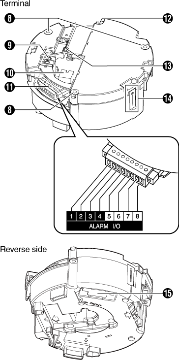
Fixing holes (x3)
This hole is for mounting the ceiling clamping bracket to the ceiling or the ceiling recessed bracket (WB-S685U: Sold separately).
[AC24V  INPUT] AC 24 V input terminal
For connecting to AC 24 V power.
[10BASE-T/100BASE-TX] LAN cable connection terminal
For connecting the unit to the network.
It supports PoE Plus (IEEE802.3at Type 2) and enables you to use this camera without having to connect to a power supply using a power cord.
Alarm Input/Alarm Output terminal (x8)
This cable is for alarm input and alarm output.
List of Alarm Pin Numbers
|
Pin Number |
Signal Name |
|---|---|
|
1 |
INPUT1 |
|
2 |
INPUT1 COM |
|
3 |
INPUT2 |
|
4 |
INPUT2 COM |
|
5 |
OUTPUT1 |
|
6 |
OUTPUT1 COM |
|
7 |
OUTPUT2 |
|
8 |
OUTPUT2 COM |
Fall prevention wire mounting hole
Mount a fall-prevention wire (sold separately) from the ceiling slab or channel to this hole to prevent the camera from falling.
Wire clamp fixing hole
This is used to bundle wires.
Fall prevention wire fixing bracket
This is for attaching the “fall prevention wire  ” of the camera.
Camera connection terminal (female)
For connecting to the connection terminal (male) of the camera.