When the display setting for [LCD/VF]  [Display On/Off] is set to “Off”, the corresponding display is hidden but it will appear for approximately 3 seconds when changes are being made.
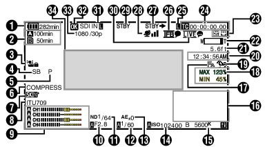
Display Screen in Camera Mode
Memo
When the display screen is turned off, it will appear only in the following cases.
Approximately 3 seconds when changes are being made
During event display or warning display
Display Screen
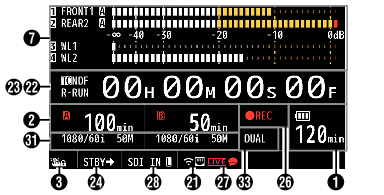
Enlarged Display
Enlarged Display (LCD Monitor Only)
Memo
Only the display on the LCD monitor is enlarged.
Voltage/Battery Power
Displays the current status of the power supply in use.
Memo
Even when the display screen is turned off and [LCD/VF] [Display On/Off] [Battery] is set to “Off”, this will be displayed when there is a warning.
Remaining Space on Media
Displays the remaining recording time for the recording media in slot A and slot B separately.
 :
:
Currently selected slot. (White card)
 :
:
Write-protect switch of SD card is set.
!INVALID:
SD card cannot be read or written to, or restored.
!FORMAT:
SD card requires formatting.
!RESTORE:
SD card requires restoring.
!INCORRECT:
When the SD card is not supported.
When an SD card lower than Class 10 is inserted while in the XHQ mode.
!REC INH:
When attempting to record more than 4 GB while a media that does not support recording of more than 4 GB is inserted.
The following icons are displayed during FTP upload.
|
Icon |
Status |
|---|---|
 |
[Auto Upload] is configured to “On” and in the standby state. “A” is displayed at the top left corner of the icon while in the Auto FTP mode. |
 |
Auto FTP transfer is in progress. |
 |
FTP transfer is in progress. |
 (Yellow) |
Error has occurred during FTP transfer. |
Memo
The displayed time is an estimate.
Even when the display screen is hidden and [LCD/VF] [Display On/Off] [Media Remain] is set to “Off”, this will be displayed when there is a warning.
You can view the status of FTP transfer during an upload under [Upload] on the Status screen.
Operation lock
The ![]() icon appears during operation lock.
icon appears during operation lock.
Memo
The ![]() icon appears for 3 seconds after operation lock is turned off.
icon appears for 3 seconds after operation lock is turned off.
Camera Angle[Tagging] 

Displays the camera angle tagging information when [ Format] is configured to “Exchange”.
ODK[Tagging]
Displays the ODK (Offence, Defence, Kick) tagging information when [ Format] is configured to “Exchange”. It flashes in red when in the REMOVE mode.
Black Toe
Displays the Black Toe setting.
Memo
The “Normal” appears for 3 seconds after changing to Normal.
Skin Detail
![]() appears when Skin Detail is functioning.
appears when Skin Detail is functioning.
Memo
![]() appears for 3 seconds after Skin Detail is turned off.
appears for 3 seconds after Skin Detail is turned off.
Color Space Display
Displays the color space.
Memo
This can be configured in [Camera Process] [Color Space].
Audio Level Meter
Displays the audio levels for CH-1 to CH-4.
 appears on the screen when in the Auto mode.

This is grayed out when in a mode that does not support audio recording or when the audio is not supported. The CH display is grayed out in the enlarged display mode.

When in the enlarged display mode, the display changes with the setting of the [AUDIO INPUT CH1/CH2/CH3/CH4] selection switch.
Example: During 1ch and 3ch display
FRONT1: When the selection switch is set to “FRONT” and [Front Mic Select] is set to a value other than “Mono”
FR1+2: When the selection switch is set to “FRONT” and [Front Mic Select] is set to “Mono”
REAR1: When the selection switch is set to “REAR”
WL1: When the selection switch is set to “WIRELESS”
Iris F-Number
Displays F-number of the lens iris.
Memo
This item may not be displayed depending on the lens used.
A icon appears on the left side of the lens aperture value (F-number) during Auto Iris mode.
While in the Auto Iris mode, and [AE Lock] is set to “AE” or “AE/FAW”, a ![]() icon appears on the left side of the lens aperture value (F-number) during lock operation.
icon appears on the left side of the lens aperture value (F-number) during lock operation.
ND Filter Position
Displays the current ND filter position.
Shutter
The current shutter speed appears on the screen.
When the camera recorder is switched to the Full Auto shooting mode using the user button that is assigned with “Full Auto” or when it is switched to the Automatic Shutter mode with [Camera Function] [Shutter] set to “EEI”, the icon appears on the left side of the shutter speed.
Memo
The variable range of the shutter speed varies according to the video format settings.
While in the Automatic Shutter mode, and [AE Lock] is set to “AE” or “AE/FAW”, a ![]() icon appears on the left side of the shutter speed during lock operation.
icon appears on the left side of the shutter speed during lock operation.
[OFF] is displayed when the shutter is turned off or when in the Low-light shooting mode.
AE Level
Displayed when the AE function is activated.
When operated while manual operation is disabled, “AE” blinks for about 5 seconds.
Gain
You can select to display the gain in “dB” or “ISO”.
Displays the gain value when in the Manual Gain mode.
A icon appears on the left side of the gain value in the “AGC” mode.
“LUX” is displayed to the left of the gain value when in the Low-light shooting mode.
Memo
While in the “AGC” mode, and [AE Lock] is set to “AE” or “AE/FAW”, a ![]() icon appears on the left side of the gain value during lock operation.
icon appears on the left side of the gain value during lock operation.
White Balance Mode
Displays the current white balance mode.
(*****K indicates color temperature)
A *****K:
When the [WHT BAL B/A/PRST] switch is set to “A” in the Manual White Balance mode.
B *****K:
When the [WHT BAL B/A/PRST] switch is set to “B” in the Manual White Balance mode.
P *****K:
When the [WHT BAL B/A/PRST] switch is set to “PRST” in the Manual White Balance mode.
FAW:
During Full Auto White Balance mode.
![]() FAW:
FAW:
While in the Full Auto White Balance mode, and [AE Lock] is set for “FAW” or “AE/FAW” during lock operation.
Memo
When [Preset Paint], [AWB Paint] or [FAW Paint] is set to a setting other than the default value, a ![]() icon is displayed to the right of the color temperature.
icon is displayed to the right of the color temperature.
Expanded Focus/Video Signal Monitor/Return Video (PiP)
Displayed upon pressing the user button that is assigned with “Expanded Focus”, “Video Signal Monitor” and “Return Video” (PiP).
Memo
The order of display is “Expanded Focus” > “Video Signal Monitor” > “Return Video” (PiP).
Focus Assist
“  ” is displayed when auto focus is activated.
When ACCU-Focus is enabled, “ACCU ” blinks for about 10 seconds while Focus Assist starts up, after which the “ ” indicator lights up.
If recording starts while [ACCU-Focus] is active, [ACCU-Focus] will be forcibly deactivated.
Luminance Information
Displayed when the Spot Meter function is activated.
MAX:
Maximum luminance
MIN:
Minimum luminance
Zebra pattern
During zebra pattern display,  (zebra icon) is displayed on the display screen in Camera mode.
Time Display
Displays the current time.
Memo
The date/time display style can be configured in [System] [Date/Time].
When [System] [Record Set] [Time Stamp] is set to “On”, this item is not displayed.
Focus Display
Displays the approximate distance to the subject in focus during manual focus.
Memo
The displayed unit of measurement (feet or meter) can be configured in [LCD/VF] [Display Type] [Focus].
This item may not be displayed depending on the lens used.
Zoom Display
Displays the zoom position. (Zoom bar or value)

The zoom bar will only be displayed for 3 seconds after the zoom operation is activated.
The value will always be displayed. (Z00 to 99)
Memo
The mode of display (value or bar) can be configured in [LCD/VF] [Display Type] [Zoom].
This item may not be displayed depending on the lens used.
Network Connection Icon
USB connection or built-in wireless LAN connection ![]()
![]()
Set [Network] [Connection Setup] [USB/Int. WLAN] to “On”. ![]()
![]()
In the case of connecting to an external network, check the destination in [Network] [Connection Setup] [Default Gateway].
|
Icon |
Status |
|---|---|
 |
Wireless LAN connection from the host terminal (USB) is established |
 |
Wired LAN connection from the host terminal (USB) is established |
 |
Cellular adapter connection from the host terminal (USB) is established |
 |
When a USB adapter different from the connection settings is detected |
 |
Built-in wireless LAN connection is established |
|
(No display) |
When [USB/Int. WLAN] is set to “Off” When an unusable USB adapter is detected |
Memo
The icon appears blinking when the camera recorder is starting up, and is displayed in yellow while getting ready to connect.
LAN terminal connection
In the case of connecting to an external network, check the destination in [Network] [Connection Setup] [Default Gateway].
|
Icon |
Status |
|---|---|
 |
LAN terminal connection is established |
|
(No display) |
When the LAN cable is not connected |
Memo
The icon appears blinking when the camera recorder is starting up, and is displayed in yellow while getting ready to connect.
Time Code (  )/User’s Bit (
  ) Display
Displays the time code (hour: minute: second: frame) or user’s bit data.
Example of time code display:
Display Screen

Colon (:) denotes non-drop frames and dot (.) denotes drop frames.
Enlarged Display
[NDF] is displayed to the right of [TC] in the case of non-drop frames and [DF] in the case of drop frames.

Example of user’s bit display:
Display Screen

Memo
Use the [TC DISPLAY] switch to toggle between the time code display and user’s bit display.
Time Code Lock Indicator
When the built-in time code generator is synchronized to the external time code data input during the synchronization of time code with another camera recorder,  lights up.
When in the enlarged display mode, [EXT ] is shown in the TC mode display.
lights up when [TC/UB] [TC Mode] is configured to “NTP” and the unit has detected and synchronized to the NTP server. When in the enlarged display mode, [NTP ] is shown.
lights up when [TC/UB] [TC Mode] is configured to “GPS” and the unit is synchronized to GPS. When in the enlarged display mode, [GPS ] is shown. ![]()
![]()
IFB/RET Mark
Displays the status of the IFB or Return over IP.
|
Icon |
Status |
|---|---|
 |
During audio feed only |
 (Yellow) |
When an error occurs during audio feed only |
 |
During video+audio feed |
 (Yellow) |
When an error occurs during video+audio feed |
SDI/HDMI Record Trigger
STBY :
When [SDI Rec Trigger] is set to “Type-A” or “Type-B”, or [HDMI Rec Trigger] is set to “On” and recording is stopped
REC :
When [SDI Rec Trigger] is set to “Type-A” or “Type-B”, or [HDMI Rec Trigger] is set to “On” and recording is in progress
GPS Mark 
When [System] [GPS] is set to “On”, the signal reception status is displayed.
Memo
The display changes according to the signal reception sensitivity. If signals cannot be received, the  mark appears in yellow regardless of the [LCD/VF] [Display On/Off] [GPS] setting.
This item is not displayed when [GPS] is set to “Off”.
Media Status
----:
A card is not detected in the selected slot, and [Tally System] is also not set to “Studio”
STBY:
Recording standby
 REC:
REC:
Recording
REVIEW:
Clip Review
STBY  :
:
Pre Rec recording standby
REC :
Pre Rec recording
STBY  :
:
Clip Continuous Rec recording standby
REC :
Clip Continuous Rec recording
STBY (displayed in yellow):
Clip Continuous Rec recording pause
STBY  :
:
Interval Rec recording standby
STBY (displayed in red):
Interval recording pause
REC :
Interval Rec recording
STBY  :
:
Frame Rec recording standby
REC :
Frame Rec recording
STBY (displayed in yellow):
Frame Rec recording pause
STOP:
Unable to record to the card in the slot
P.OFF:
Power OFF
![]() :
:
During clip cutter recording (displayed for 3 seconds)
CALL:
Receiving call signals from an external device, such as a remote control unit
PGM:
Receiving program signals from an external device, such as a remote control unit
PVW:
Receiving preview signals from an external device, such as a remote control unit
Live streaming mark
When [Network] [Live Streaming] [Live Streaming] is set to “On”, the distribution status is displayed.
|
Icon |
Status |
|---|---|
 (Red) |
Distribution in progress (good connection quality) |
 (Red) |
Distribution in progress (poor connection quality) |
 (Yellow) |
Waiting for connection (RTSP/RTP only), connection failed |
SDI Input Mode/High-Speed Frame Rate
“SDI IN ” is displayed when a device is connected to the [HD/SD SDI IN] terminal, and [System] [Record Set] [Record Format] [System] is set to “HD(SDI In)” or “SD(SDI In)”.
When [System] [Record Set] [Record Format] [System] is configured to “High-Speed”, the setting value for [ Frame Rate] is displayed.
OK Mark
Displayed when OK mark has been appended.
Recording Format/Bit Rate (Enlarged Display Mode Only)
Displays the recording format and bit rate (only when in the enlarged display mode).
Memo
The resolution, frame rate and bit rate can be viewed on the status screen.
Event/Warning Display Area
Displays error messages.
Dual Rec/ Backup Rec Display (Enlarged Display Mode Only)
“DUAL” is displayed in the Dual Rec mode and “BACKUP” is displayed in the Backup Rec mode.
Memo
Displayed only when in the enlarged display mode.
![]()