> Preparation > Name and Function of Parts
Name and Function of Parts
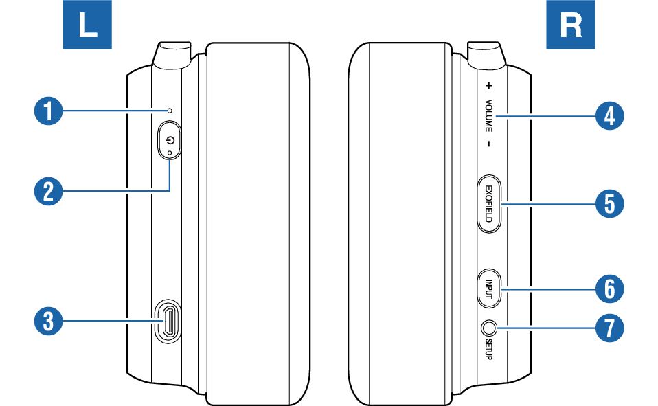
Headphone
-
Indicator
-
Power button (
 )
) -
Micro USB charging terminal
-
Volume (Capacitive touch sensor)
-
EXOFIELD button
-
INPUT button
-
SETUP terminal
Displays the operating status of the headphones.
Switches on/off the power.
For connecting the supplied micro USB cable to charge the headphones.
Slide your finger over the sensing range of the capacitive touch sensor to adjust the volume.
Switches on/off the EXOFIELD effect.
Switches the input.
Pressing and holding the button displays the settings and status on the TV screen.

Connect the supplied setup cable to this terminal for EXOFIELD measurement.
Processor Unit
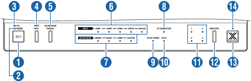
Top
-
Power button (
 )
) -
Power indicator (STANDBY)
-
Power indicator (AUTO)
-
INPUT/INFO button
-
SOUND MODE/PAIRING button
-
INPUT indicators
-
SOUND MODE indicators
-
BT CONNECTION indicator
-
DOLBY ATMOS indicator
-
DTS:X indicator
-
User data indicators
-
USER DATA button
-
EXOFIELD button
-
EXOFIELD indicator
Pressing the button each time toggles the power between on and standby. Pressing the holding the button enables/disables connection of the processor unit with the power of the headphones. About the Auto Standby and Standby Modes
Lights up when the power is in the standby state. Light goes off when the power is on or off.
Lights up when processor unit and headphone power synchronization is enabled, and light off when it is disabled. Light is also off when the power is on.
Switches the input.
Pressing and holding the button displays the settings and status on the TV screen.
Switches the sound mode. This button is also used for pairing with a smartphone.

The selected input lights up.
The selected sound mode lights up. All the lights are off when in the FLAT mode.
Lights up when connected to a smartphone via BLUETOOTH.
Light flashes while in the pairing mode.
Lights up while decoding DOLBY ATMOS format.
*When the EXOFIELD effect is off, this indicator won’t light up even if the content is DOLBY ATMOS.
Lights up while decoding DTS:X format.
The selected user data lights up.
Switches the user data.

Switches on/off the EXOFIELD effect.
Lights up when the EXOFIELD effect is on.
Front

-
SETUP terminal
Connect the supplied setup cable to this terminal for EXOFIELD measurement.
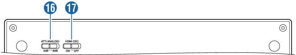
Bottom
-
ATT(ANALOG) switch
-
HDMI CEC switch
Switch to 0 dB if the audio of the analog connection device is too soft.
Turning on CEC (Consumer Electronics Control) links the headphones to another device connected via HDMI and enables power to be turned on or off.
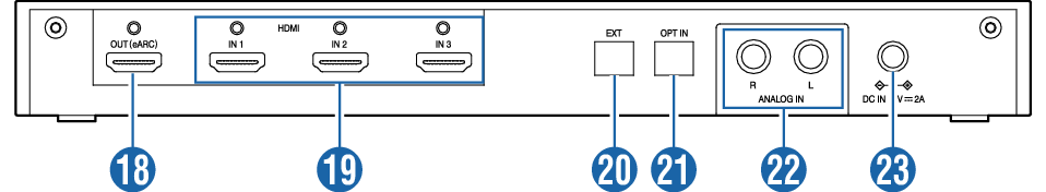
Rear
-
HDMI output terminal
-
HDMI input terminals
-
EXT terminal
-
OPT IN terminal
-
ANALOG IN terminals (R/ L)
-
Power terminal
This is the HDMI output terminal. Supports eARC/ ARC.
This is the HDMI input terminal. There are three terminals in total (IN 1/ IN 2/ IN 3).
This is the terminal for service use only.
This is the optical digital (SPDIF) audio input terminal.
These are the analog audio input terminals.
Connect the supplied AC adapter to this terminal.