Mounting the Camera (VN-H657BU)
TOPEnsure that the connection cables are not caught in between and secure the ceiling mount section to the ceiling with 3 screws.
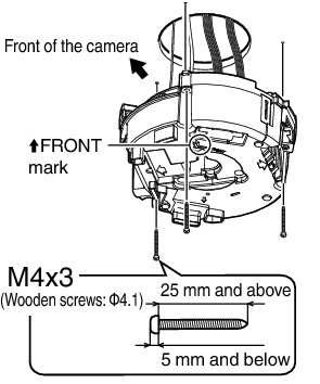
Use M4 fixing screws and bolts.
Use Φ4.1 wooden screws.
The length of the screws should be 25 mm (1inch) and above.
Place and install the product horizontally. The camera will not operate properly if it is slanted.
The screw head should be 5 mm and below. If the ceiling structure is metal, image noise may occur.
Do not use screws for which the screw head is embedded after fastening. (e.g. flat countersunk head screws). Otherwise, the insulating resin part may be damaged, thus preventing proper insulation.
Always use three screws and mount securely.
Tighten the screws again during maintenance just to be safe.
The plastic parts on the ceiling fixing holes of the ceiling mount section act as an insulation between the ceiling mount section and the ceiling structure. If the ceiling structure is metal and insulation is not provided between the camera and the ceiling structure, image noise may occur. Be sure to provide insulation.
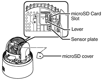
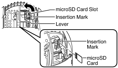
Get ready a formatted microSD card in advance.
Refer to the following page for the types of microSD cards compatible with this camera.
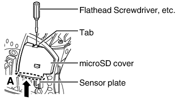
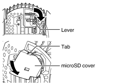
If it is hard to remove the microSD cover, press an object such as a flathead screwdriver against the tab to remove it.
Align the orientation of the microSD card with the insertion mark, and insert it all the way in until it clicks into place.
To attach the microSD cover, attach the tab, followed by pushing it in the direction of the arrow.
The lens unit (camera module) may turn easily. Keep it in position using your hand without touching the lens.
To remove the microSD card, follow the same steps during insertion to remove the microSD cover and take out the card.
Pushing the microSD card inward ejects it.
To insert or replace a microSD card, do so after turning off the power of the camera.
While writing to the microSD card is in progress, turning off the power or removing the card may damage the data stored inside it.
Before removing the microSD card, press the [Unmount] button on the [microSD Card Recording] page to unmount it.
When removing the microSD cover or the microSD card, exercise care to prevent injury caused by the tools or metal around the microSD cover.
When removing or attaching the microSD cover, pay attention not to scratch the sensor plate, or cause it to deform with excessive force.
When removing the microSD card from the card slot, it may sometimes pop out forcefully. Be careful not to lose it.
When inserting or replacing a microSD card, be careful not to drop the microSD cover or microSD card.
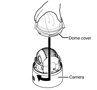
The dome cover is an optical part. Handle with care.
Prevent any dirt or foreign object from entering when mounting the dome cover.
Tighten the dome cover securely.
Be sure to turn the dome cover until it stops and tighten securely. Make sure that the dome cover is not slanted.
Do not over-rotate the dome cover. This may damage the dome cover.
If it is difficult to screw on the dome cover, turn it in an anticlockwise direction until you hear a click sound, then turn it in a clockwise direction. It will screw on smoothly.
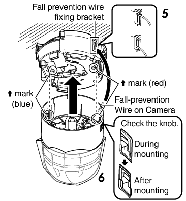
Mount the fall prevention wire, which is attached to the camera, to the fall prevention wire fixing bracket of the ceiling mount section.
The camera may fall if the fall prevention wire is not connected. Be sure to connect the fall prevention wire.
For safety purposes, do not leave the fall prevention wire dangling by the camera.
Align the “ ![]() mark (blue)/(red)” inside the camera with the “
mark (blue)/(red)” inside the camera with the “ ![]() mark (blue)/(red)” on the ceiling mount section.
mark (blue)/(red)” on the ceiling mount section.
Mount the camera securely by inserting it into the ceiling mount section until you hear a click sound.
If the camera is mounted on securely, the camera fixing lock knobs (x2) will stick out a little.
Before mounting the camera, check that the camera fixing lock knobs are not locked (i.e., lock knobs are on top). The camera cannot be mounted if the lock knobs are locked.
When pulling out the cables from the side, remove the cable cover of the camera.
When the camera is mounted on the ceiling mount section, lower the camera fixing lock knobs (x2) in the direction of the arrow and secure the camera such that it does not fall off.
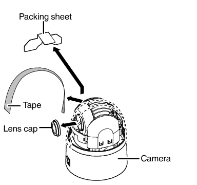
After installation is complete, peel off the dome cover protection sheet.
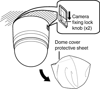
The camera may fall if the camera fixing lock knobs (x2) are not locked. Be sure to check that the lock knobs are firmly locked.
Improper mounting may cause the camera to fall off. After mounting, check that the camera is mounted securely.
Installation of the camera is complete. Next, set the IP address of the camera.