Power cord for connecting to AC 24 V (Reference value)
Installation and Connection Preparations (VN-H657BU)
TOPBe sure to put on protective glasses to protect your eyes from falling objects when mounting the camera.
The fall prevention wire (for ceiling) is not supplied. Please purchase the fall prevention wire separately beforehand.
Make holes on the ceiling (use the provided template) and pull out the cables from the holes.
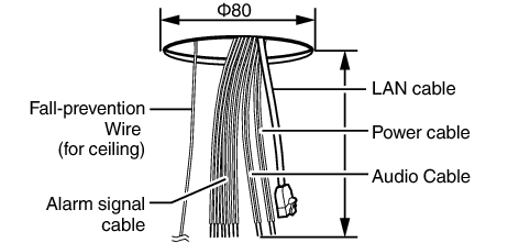
Use the provided template to make a hole (Φ80 mm) for the connection cables to thread behind the ceiling.
If necessary, also open a screw hole to mount the ceiling mount section to the ceiling. In this case, align the “ ![]() FRONT mark” of the template in the direction where the camera faces front and open the screw hole.
FRONT mark” of the template in the direction where the camera faces front and open the screw hole.
Pull out from the ceiling the fall prevention wire (for ceiling), power cable, LAN cable, alarm signal cable, audio cable, etc. that were mounted to the ceiling slab.
Note
Mount the fall-prevention wire (for ceiling) to a location that has sufficient strength.
Remove the ceiling mount section from the camera unit.
The ceiling mount section is attached to the camera unit during packaging of the product. Before installing the camera, remove the ceiling mount section from the camera unit.
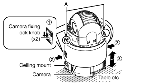
Release the locks by sliding them in the direction indicated by the arrows
Push the lock knobs inward from both the left and right directions as indicated by the two arrows.
(If the camera fixing lock knob is too stiff, push the knob hard while pressing the edge of the camera unit (A in the diagram) against the table you are using.)
(If the camera fixing lock knob is too stiff, push the knob hard while pressing the edge of the camera unit (A in the diagram) against the table you are using.)
Lift the camera unit upward to detach.
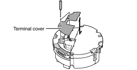
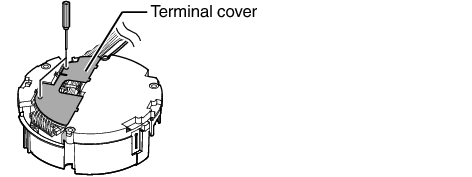
Remove the terminal cover.
Loosen the two screws on the ceiling mount section and remove the terminal cover.
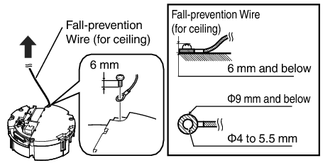
Mount the fall prevention wire (for ceiling; to connect the ceiling mount section to the ceiling).
Note
Take note of the length, strength, pull and material (insulation) of the fall prevention wire (for ceiling) and use one with a wire strength of more than 20 k  .
.
The inner diameter of the ring section of the fall prevention wire mounted on the camera should be Φ4 mm and above and Φ5.5 mm and below, and the outer diameter should be Φ9 mm and below.
The thickness of the screw head and the wire (including the washer) should be 6 mm and below. If it is more than 6 mm, the screw will touch the ceiling and the camera cannot be installed horizontally.
Use M4 fixing screws.
Memo
The wire should be insulated from the ceiling structure. If the ceiling structure is metal and insulation is not provided between the camera and the ceiling structure, image noise may occur.
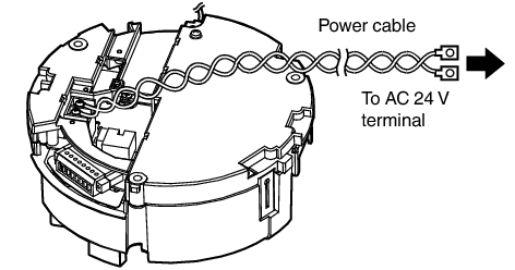
Connect the power cable.
To supply power from an AC 24 V power supply, connect a power cable.
To supply power via PoE plus, you do not need to connect a power cable. Go to the next step.
|
Conductor Diameter (mm) |
Maximum connection distance (m) |
|---|---|
|
Φ1.0 and above |
40 |
|
Φ1.6 and above |
130 |
|
Φ2.0 and above |
200 |
|
Φ2.6 and above |
350 |
Memo
The default IP address setting is 192.168.0.2.
Note
For safety reasons, turn on the power only after ensuring that all the connections are in place.
If power is supplied from both power cable and LAN cable, priority will be given to the power supply from the power cable.
If multiple cameras are turned on simultaneously in the same LAN environment, access attempts may fail due to IP address duplication. Set up an IP address by either using the JVC-VN-IP SettingTool (included on the supplied CD-ROM) or turning the power supply of each camera on separately to avoid duplication.
Caution
To supply power to this product, make use of AC 24 V 50 Hz/60 Hz or PoE Plus (IEEE802.3at Type2). Make use of the correct voltage.
Be sure to use an AC 24 V supply that is isolated from the primary power supply circuit.
Supplying a power beyond the rated value may result in failures, smoke or fire. If the camera breaks down, turn off the power and contact our service center immediately.
When a power beyond the rated value is supplied, the internal components may be damaged even if no abnormality is found on the appearance and operation of the camera. Please contact our service center immediately for servicing (charged separately).
Connect the LAN cable.
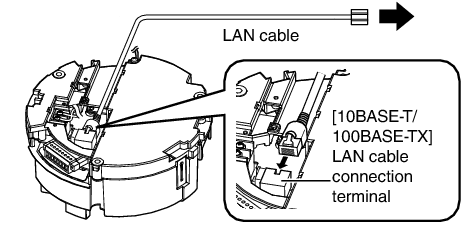
Connect the camera to a hub or computer using a LAN cable.
When connecting to a hub: Make use of a straight cable.
When connecting to a computer: Make use of a cross cable.
LAN cable to use
STP (Recommended shield cable)
Length of 100 m or shorter
Category 5e and above
Note
Cross cables cannot be used with some computers. When connecting the camera directly to a computer, check the computer’s LAN specifications in advance.
Connect the alarm signal cable to the alarm signal terminal.
Connect the alarm signal terminal to external devices, such as a sensor or buzzer.
For information on the pin number and signal name of the alarm signal, refer to the following.
Fore more details on alarm input/output, refer to the following.
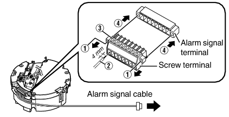
Loosen screws on both sides of the screw terminal with a flathead screwdriver, and remove the screw terminal.
Memo
You can remove the screw terminal easily by inserting the tip of the screwdriver into the slit of the screw terminal.
Peel off about 4 mm of the alarm signal cable covering, and insert the cable into the screw terminal.
Memo
If the cable cannot be inserted, turn the screw located on the side of the screw terminal in the anti-clockwise direction.
Turn the screws at the side to secure the alarm signal cable.
When the alarm signal cable is secured, return the screw terminal that was removed in  to its original position.
to its original position.Alarm signal cable to use
Length of 50 m or shorter
UL1007, UL1015 or equivalent products
AWG#22 to AWG#18 or equivalent products
Note
Noises from an external source may cause the camera to malfunction even when the cable used is within 50 m. In this case, move the cable away from the noise source.
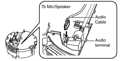
Connect the audio cable.
Get ready a separate cable for connecting to the audio device.
After connecting the audio cable (supplied) to the audio terminal of the camera, connect the cable of the audio equipment with the supplied audio cable by soldering or crimping, and wrap the joint with insulation tape.
Audio cable (brown/white) (mic input):
Connect with the cable from devices such as a capacitor microphone that supports plug-in power.
Audio cable (black/white) (line output):
Connect with the cable from devices such as speakers with a built-in amplifier.
For information on the color and signal name of the audio cable, refer to the following.
Cable for connecting to the audio device (microphone input/line output)
Shielded cable recommended
Length of 5 m or shorter recommended
Note
When connecting the audio cable (supplied) to the audio terminal, pay attention to the direction of the connector.
After connection of the cables is complete, bundle them with a wire clamp (supplied).
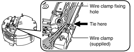
Note
To prevent the cables from tangling and coming off, be sure to thread a wire clamp through the wire clamp fixing hole to tie the cables.
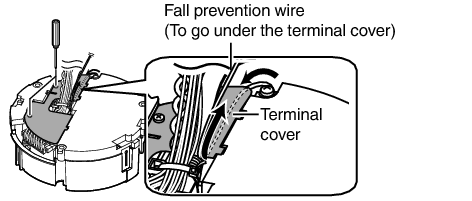
Mount the terminal cover.
Return the terminal cover that was removed in step 3 to its original position. The direction to pull out the cables changes according to the mounting method of the camera.
Pulling out the cables from the side
Pulling out the cables from the top
Note
Be sure to mount the terminal cover to prevent foreign objects or dust from entering.
When pulling out the cables from the top, make sure the fall prevention wire go under the terminal cover and pull it out together with the other cables.
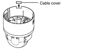
When pulling out the cables from the side, remove the cable cover of the camera.
Preparation for installation and connection is now complete. Next, mount the camera unit.