Mounting the Camera (VN-H657WPBU)
TOPMount the fall prevention wire of the camera to the fall prevention wire anchor bolt that was installed earlier.
Secure the fall prevention wire tightly with a nut and washer.
Mount the camera to the camera anchor bolts that were installed earlier.
Secure the camera tightly with a nut and washer.
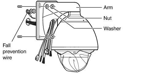
This product weighs approximately 5.6 k  . Mount the camera while paying careful attention to prevent it from falling.
For your safety, hold the arm section during installation.
After installing, paint the nuts and washers to prevent corrosion.
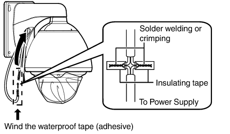
To supply power from an AC 24 V power supply, connect a power cable.
To supply power via PoE plus, you do not need to connect a power cable. Go to the next step.
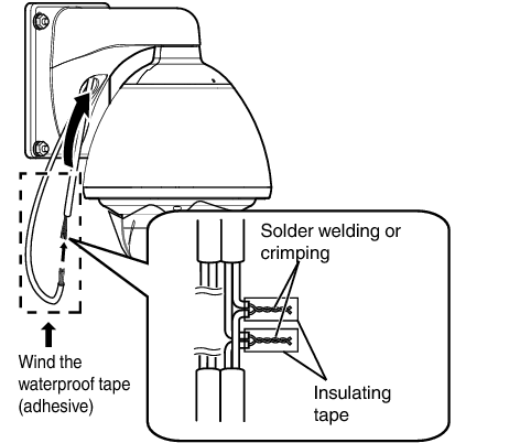
After connecting the power cable, wind the waterproof tape (adhesive).
After connecting, push the power cable into the arm of the camera.
Power cord for connecting to AC 24 V (Reference value)
|
Conductor Diameter (mm) |
Maximum connection distance (m) |
|---|---|
|
Φ1.0 and above |
20 |
|
Φ1.6 and above |
60 |
|
Φ2.0 and above |
100 |
|
Φ2.6 and above |
180 |
The default IP address setting is 192.168.0.2.
For safety reasons, turn on the power only after ensuring that all the connections are in place.
If power is supplied from both power cable and LAN cable, priority will be given to the power supply from the power cable.
If multiple cameras are turned on simultaneously in the same LAN environment, access attempts may fail due to IP address duplication. Set up an IP address by either using the JVC-VN-IP SettingTool (included on the supplied CD-ROM) or turning the power supply of each camera on separately to avoid duplication.
To supply power to this product, make use of AC 24 V 50 Hz/60 Hz or PoE Plus (IEEE802.3at Type2). Make use of the correct voltage.
Be sure to use an AC 24 V supply that is isolated from the primary power supply circuit.
Supplying a power beyond the rated value may result in failures, smoke or fire. If the camera breaks down, turn off the power and contact our service center immediately.
When a power beyond the rated value is supplied, the internal components may be damaged even if no abnormality is found on the appearance and operation of the camera. Please contact our service center immediately for servicing (charged separately).
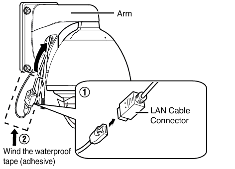
When connecting to a hub: Make use of a straight cable.
When connecting to a computer: Make use of a cross cable.
LAN cable to use
STP (Recommended shield cable)
Length of 100 m or shorter
Category 5e and above
Connect to an AC 24 V power supply when using the VN-H657WPBU in an environment below -10 °C. When power is supplied using PoE Plus, the heater will not work.
Cross cables cannot be used with some computers. When connecting the camera directly to a computer, check the computer’s LAN specifications in advance.
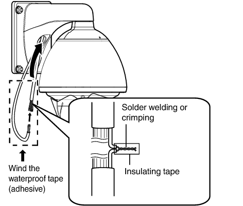
Connect the alarm signal cable to external devices, such as a sensor or buzzer.
For information on the color and signal name of the alarm signal cable, refer to the following.
Fore more details on alarm input/output, refer to the following.
After connecting the alarm signal cable, wind the waterproof tape (adhesive).
After connecting, push the alarm signal cable into the arm of the camera.
Alarm signal cable to use
Length of 50 m or shorter
UL1007, UL1015 or equivalent products
AWG#22 to AWG#18 or equivalent products
For cables that are not used, be sure to wrap the ends individually with waterproof tape (adhesive) to ensure that waterproof treatment is performed.
For safety reasons, turn on the power only after ensuring that all the connections are in place.
Noises from an external source may cause the camera to malfunction even when the cable used is within 50 m. In this case, move the cable away from the noise source.
Get ready a separate cable for connecting to the audio device.
Connect the cable of the audio equipment with the audio cable of the camera by soldering or crimping.
Audio cable (white/white) (mic input):
Connect with the cable from devices such as a capacitor microphone that supports plug-in power.
Audio cable (light green/light green) (line output):
Connect with the cable from devices such as speakers with a built-in amplifier.
For information on the color and signal name of the audio cable, refer to the following.
Connect the audio cable, followed by winding the waterproof tape (adhesive).
After connecting, push the audio cable into the arm of the camera.
Cable for connecting to the audio device (microphone input/line output)
Shielded cable recommended
Length of 5 m or shorter recommended
For cables that are not used, be sure to wrap the ends individually with waterproof tape (adhesive) to ensure that waterproof treatment is performed.
For safety reasons, turn on the power only after ensuring that all the connections are in place.
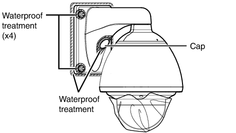
Ensure that waterproof treatment is performed. Otherwise, the camera may malfunction due to rain water seepage.
Use GE silicon or other similar product for the sealing material.
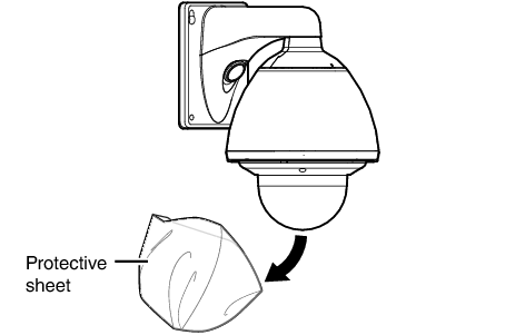
Installation of the camera is complete. Next, set the IP address of the camera.