Be sure to put on protective glasses to protect your eyes from falling objects when mounting the camera.
Installation and Connection Preparations (VN-H657WPBU)
TOPSetting Up the Wall
Make a hole in the wall.
Make a hole (Φ45 mm) for the connecting cables to pass through.
Note
Check the strength of the wall. A less firm wall may cause the unit to fall.
Install the anchor bolts for mounting the camera.
Install 4 anchor bolts (M8  35 mm and above) to mount the camera.
Install the anchor bolt for mounting the fall prevention wire.
Install the anchor bolt to mount the fall prevention wire 30 mm below the center of the upper two anchor bolts that are used to mount the camera.
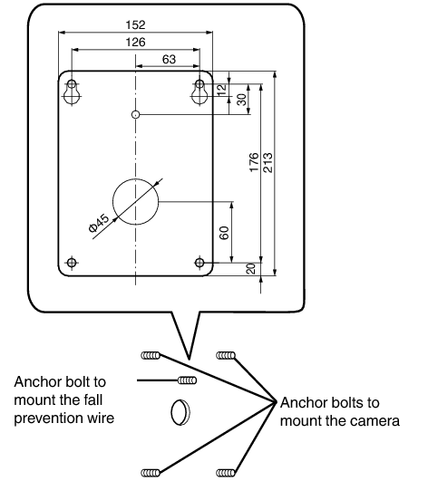
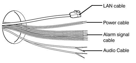
Pull the cables from the hole in the wall.
Pull the power cable, LAN cable, alarm signal cable, and audio cable from the wall.
Setting Up the Camera
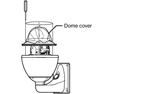
Remove the dome cover.
Loosen the screws (x4) and remove the dome cover from the camera.
Remove the lens cap and tape used during transporting.
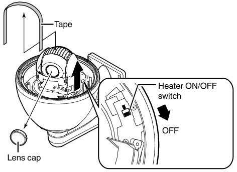
Memo
When installing the heater at an unrequired location, turn off the ON/OFF switch of the heater.
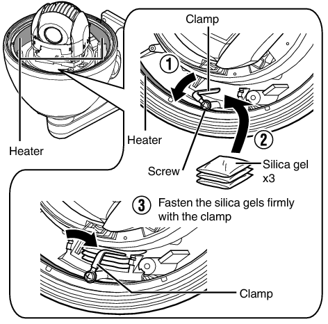
Insert the silica gels.
Be sure to insert the provided silica gels in the position as shown in the diagram.
Loosen the screw and lift up the clamp.
Take out three silica gels from the aluminum bag, and insert them into the back of the heater (as shown in the diagram).
After inserting the silica gels, check that they are not touching the heater.
Fix the silica gels firmly with the clamp, and fasten the screw.
Turn the clamp until the silica gels are secured, followed by tightening the screw.
Memo
During reconnection or re-installation after repair or maintenance, make sure to replace the silica gels with new ones.
Consult our service center on the replacement procedures. Use the silica gel with a service part number of LW40500-001A for the part to be replaced.
Note
If silica gel is not inserted, the camera lens and dome cover may turn foggy, and the camera image may not turn out clear.
When installing on a rainy day, ensure that raindrops do not enter the interior.
Insert a microSD card. (VN-H657WPBU)
Get ready a formatted microSD card in advance.
Refer to the following page for the types of microSD cards compatible with this camera.
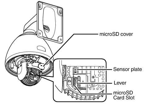
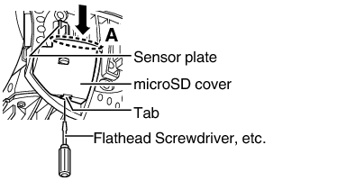
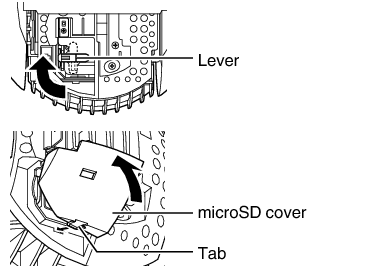
Remove the microSD cover by lifting the part indicated by A in the direction of the arrow.
If it is hard to remove the microSD cover, press an object such as a flathead screwdriver against the tab to remove it.
Turn the lever by 90 ° in the anti-clockwise direction, and insert the microSD card into the microSD card slot.
Align the orientation of the microSD card with the insertion mark, and insert it all the way in until it clicks into place.
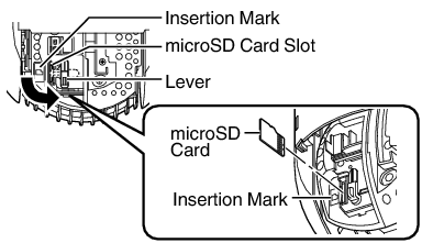
Turn the lever by 90 ° in the clockwise direction to attach the microSD cover.
To attach the microSD cover, attach the tab, followed by pushing it in the direction of the arrow.
Memo
The lens unit (camera module) may turn easily. Keep it in position using your hand without touching the lens.
To remove the microSD card, follow the same steps during insertion to remove the microSD cover and take out the card.
Pushing the microSD card inward ejects it.
Note
To insert or replace a microSD card, do so after turning off the power of the camera.
While writing to the microSD card is in progress, turning off the power or removing the card may damage the data stored inside it.
Before removing the microSD card, press the [Unmount] button on the [microSD Card Recording] page to unmount it.
When removing the microSD cover or the microSD card, exercise care to prevent injury caused by the tools or metal around the microSD cover.
When removing or attaching the microSD cover, pay attention not to scratch the sensor plate, or cause it to deform with excessive force.
When removing the microSD card from the card slot, it may sometimes pop out forcefully. Be careful not to lose it.
When inserting or replacing a microSD card, be careful not to drop the microSD cover or microSD card.
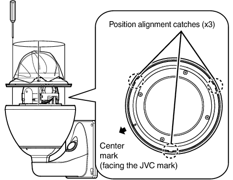
Mount the dome cover to the camera.
Use the screws (x4) to mount the dome cover to the camera. When installing the dome cover, make use of the three catches and the center mark of the cover as a guide. Install such that the central mark appears above the JVC mark of the camera.
Note
Check that there is no dirt or dust inside the dome cover before mounting.
When installing on a rainy day, ensure that raindrops do not enter the interior.
When mounting the dome cover, temporarily secure the four screws and then tighten.
As a guide, tighten the screws to 0.5 N·m to 1 N·m (5 kgf·cm to 10 kgf·cm). If the screws are insufficiently tightened, the dome cover may fog due to moisture penetration.
Remove the cable connection cap.
Remove the cap on the arm of the camera.
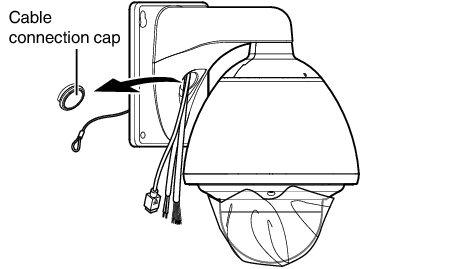
Pull out the cables from the cable connection hole.
Pull out the cables (except the fall prevention wire) of the camera from the cable connection hole.
Preparation for installation and connection is now complete. Next, mount the camera unit.