Inputting External Synchronizing Signals (Genlock)
TOPA [GENLOCK] terminal is available on the side of the camera recorder.
You can input synchronizing signals from a KA-M790G unit (Multicore Remote Adapter: sold separately) that is connected to the accessory connection terminal (68 pins) on the rear of the camera recorder. 

SDI signals (digital signals) can be input from the [HD/SD SDI IN] terminal on the side.
Input external synchronizing signals from the [GENLOCK] terminal and [HD/SD SDI IN] terminal ( ), and synchronize the camera video with the external signal.
The H (Horizontal) Phase of the camera recorder’s video signals can be adjusted with respect to the external synchronizing signals on the [A/V Set]  [Video Set] [Genlock Adjust] screen.
The genlock feature is only usable in the Camera mode.
Genlock Signal Settings
For analog signal input
 Synchronizing signal used
SD synchronizing signal:
BB (Black Burst) signal
Supports SMPTE170M (RS-170A)-NTSC
Supports ITU-R BT.470-6 PAL
HD synchronizing signal:
HDTV tri-level synchronizing signal
Supports SMPTE296M-HD720p
Supports SMPTE274M-HD1080i
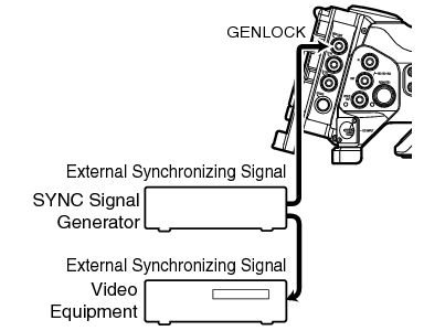
Set [A/V Set] [Video Set] [Genlock Input] to “BNC”.
Set to “Adapter” to input synchronizing signal from the accessory connection terminal (68 pins) on the rear of this unit.
When the camera recorder’s video is locking to the external synchronizing signal, “Sync Locking” appears on the screen.
After locking to the external synchronizing signal is complete, the display disappears and recording can be performed.
If there is genlock signal input but the signal format is not supported, “Invalid Sync” is displayed.
If the frame rate of [  Frame & Bit Rate]/[
  Frame & Bit Rate] in the [Record Format] menu is set to “60p”, “60i”, “30p”, or “24p”, 59.94 Hz synchronizing signals (vertical synchronization) are input.
50 Hz/60 Hz synchronizing signals are not synchronized.
If the frame rate of [ Frame & Bit Rate]/[ Frame & Bit Rate] in the [Record Format] menu is set to “50p”, “50i”, or “25p”, 50 Hz synchronizing signals (vertical synchronization) are input.
59.94 Hz/60 Hz synchronizing signals are not synchronized.
Do not connect or disconnect the input cable for the synchronizing signals during recording or playback
If the power is turned on during input of external synchronizing signals, vertical oscillation may occur. This is not a malfunction.
Signals such as VTR playback signals with jitters may not be synchronized on this camera recorder.
Only H (Horizontal) and V (Vertical) genlock functions are available on this camera recorder. It does not come with a lock function for SC (sub-carrier). Color flash may occur during switching such as when composite signals are used by a switcher.
Phase Items to Synchronize
The phase items to be synchronized may vary depending on the input synchronizing signal and output video signal.
|
Output Video Signal |
Input Synchronizing Signal |
|||
|---|---|---|---|---|
|
BB |
Tri-sync |
|||
|
720p |
1080i |
|||
|
VIDEO |
Composite |
H, V, F |
V |
V, F |
|
Y/PB/PR |
SD Component |
H, V, F |
V |
V, F |
|
HD Component 720p |
V |
H, V |
V |
|
|
HD Component 1080i |
V, F |
V |
H, V, F |
|
|
HD/SD SDI |
SD-SDI |
H, V, F |
V |
V, F |
|
HD-SDI 720p |
V |
H, V |
V |
|
|
HD-SDI 1080i |
V, F |
V |
H, V, F |
|
H:
Horizontal Phase
V:
Vertical Phase
F:
Field Phase
For digital signals (SDI) input
Input external synchronizing signals from the [HD/SD SDI IN] terminal, and synchronize the camera video with the external signal.
Synchronizing signal used
SD synchronizing signal:
Supports SMPTE259M
HD synchronizing signal:
Supports SMPTE292M
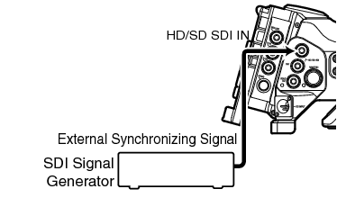
Set [A/V Set] [Video Set] [Genlock Input] to “SDI”.
Set to “Adapter” to input synchronizing signal from the accessory connection terminal (68 pins) on the rear of this unit.
When the camera recorder’s video is locking to the external synchronizing signal, “Sync Locking” appears on the screen.
After locking to the external synchronizing signal is complete, the display disappears and recording can be performed.
If there is genlock signal input but the signal format is not supported, “Invalid Sync” is displayed.
If the frame rate of [ Frame & Bit Rate]/[ Frame & Bit Rate] in the [Record Format] menu is set to “60p”, “60i”, “30p”, or “24p”, 59.94 Hz synchronizing signals (vertical synchronization) are input.
50 Hz/60 Hz synchronizing signals are not synchronized.
If the frame rate of [ Frame & Bit Rate]/[ Frame & Bit Rate] in the [Record Format] menu is set to “50p”, “50i”, or “25p”, 50 Hz synchronizing signals (vertical synchronization) are input.
59.94 Hz/60 Hz synchronizing signals are not synchronized.
Do not connect or disconnect the input cable for the synchronizing signals during recording or playback
If the power is turned on during input of external synchronizing signals, vertical oscillation may occur. This is not a malfunction.
Signals such as VTR playback signals with jitters may not be synchronized on this camera recorder.
Only H (Horizontal) and V (Vertical) genlock functions are available on this camera recorder. It does not come with a lock function for SC (sub-carrier). Color flash may occur during switching such as when composite signals are used by a switcher.
Phase Items to Synchronize
The phase items to be synchronized may vary depending on the input synchronizing signal and output video signal.
|
Output Video Signal |
Input Synchronizing Signal |
|||
|---|---|---|---|---|
|
SD-SDI |
HD-SDI |
|||
|
720p |
1080i |
|||
|
VIDEO |
Composite |
H, V, F |
V |
V, F |
|
Y/PB/PR |
SD Component |
H, V, F |
V |
V, F |
|
HD Component 720p |
V |
H, V |
V |
|
|
HD Component 1080i |
V, F |
V |
H, V, F |
|
|
HD/SD SDI |
SD-SDI |
H, V, F |
V |
V, F |
|
HD-SDI 720p |
V |
H, V |
V |
|
|
HD-SDI 1080i |
V, F |
V |
H, V, F |
|
Adjusting H Phase
Adjust the [A/V Set] [Video Set] Genlock Adjust item as follows.
[Analog SD H Phase]:
Adjusts the H Phase of the SD analog signal.
[Analog HD H Phase] :
Adjusts the H Phase of the HD analog signal.
[SD-SDI H Phase]:
Adjusts the H Phase of the SD SDI signal.
[HD-SDI H Phase]:
Adjusts the H Phase of the HD SDI signal.

 ).
).The H Phase of the camera recorder’s video signal is adjusted with respect to the external synchronizing signal input from the [GENLOCK] terminal.
The setting value of the [Analog HD H Phase] , [SD-SDI H Phase], and [HD-SDI H Phase] items can be adjusted in increments of 10 by pressing the cross-shaped button ( ) for 2 seconds or longer.
Adjustment cannot be made while recording or playback is in progress.
The video image may be disrupted momentarily during adjustment. This is not a malfunction.


